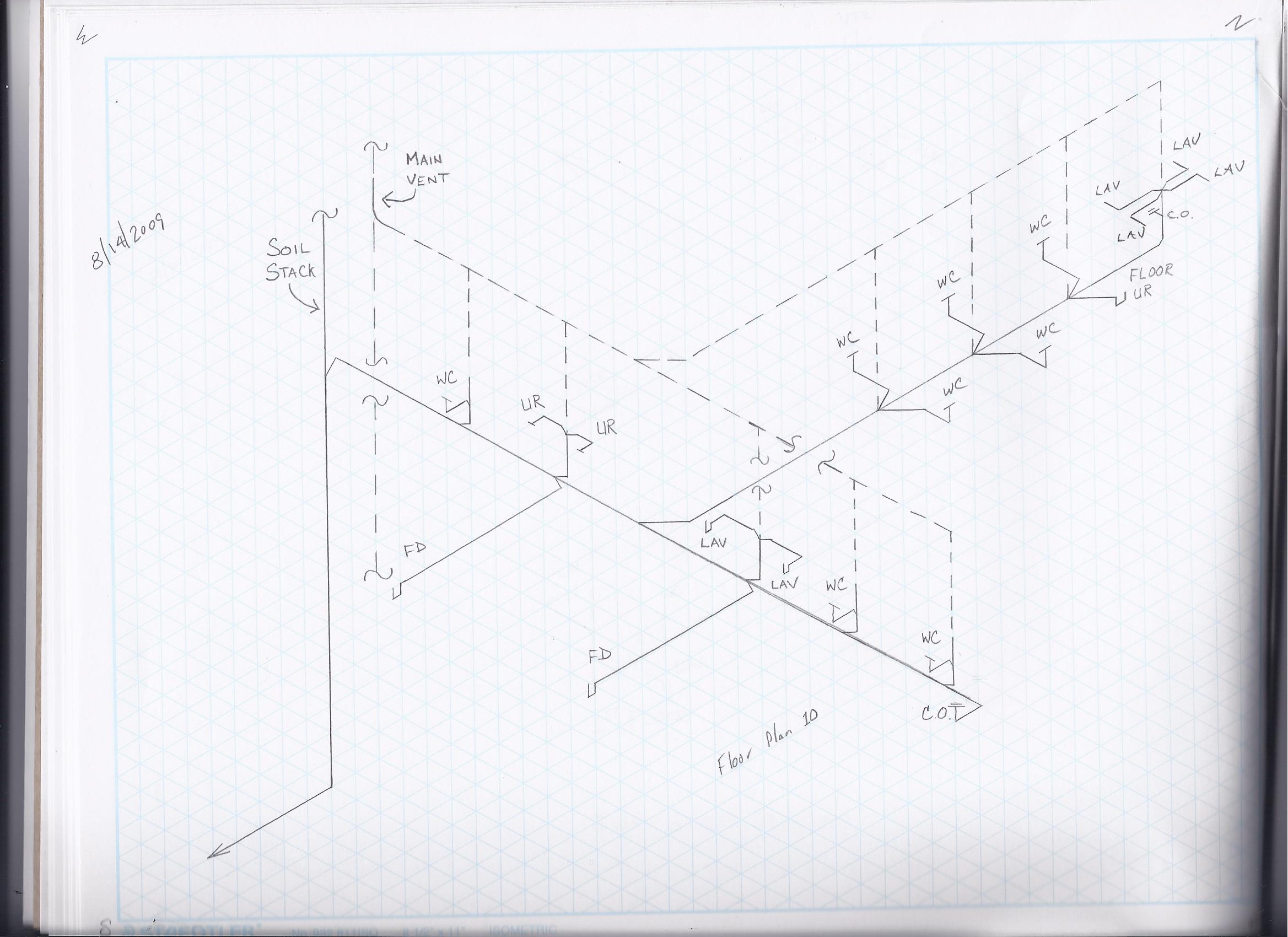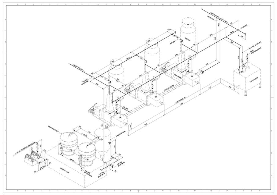

This is the information required to present both Plan and Isometric views from the respective options in the Software´s Results tab. In pipes, automatically will be assigned to its start and end points, the coordinates of the respective nodes, being possible to further add interior vertices so as to define the points of change in horizontal alignment:

In the case of ‘conventional nodes,’ that is, those without associated sanitary fixtures, only the introduction of one pair of coordinates is required, depending on the network to which it belongs (cold or hot water). In the case of nodes with sanitary fixtures supplied from cold and hot water systems, specifying two pairs of coordinates will be needed to in order to identify the location of the respective supplying points to the sanitary fixture in question: With projects created in the previous version of PLUMBER (1.0), as well as those that are created without using the aforementioned importing option, the coordinates values have to be manually specified by the user in nodes and pipes data dialogs in order to benefit from this great feature. In the case of water networks created by importing files in DXF format these values will be taken from the graphic properties of the imported drawing objects. The Plan and Isometrics views creation in PLUMBER 2.0 is conditioned upon, at least, that the nodes that make up the water supply system have values other than 0 for its X and Y coordinates. You will see below this new feature’s details. With version 2 of PLUMBER, our software for water supply systems design in buildings, it is now possible to create Plan and Isometrics views of the water network you are designing.


 0 kommentar(er)
